
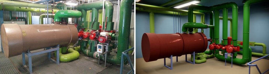
A digital twin (Digital Twin) is a virtual model of a product, process, or service. It can be used to visualize the operation of the object and its related information. Digital Twins for Leveraging Renewable Energy (DUKE) project, funded by Lapin Liitto and executed by the Lapland University of Applied Sciences, has its first functional pilot done in the Lapland Education Centre REDU’s educational heating plant in Jänkätie, Rovaniemi. It will be implemented with the Unity 3D game engine.
The game engine is powerful
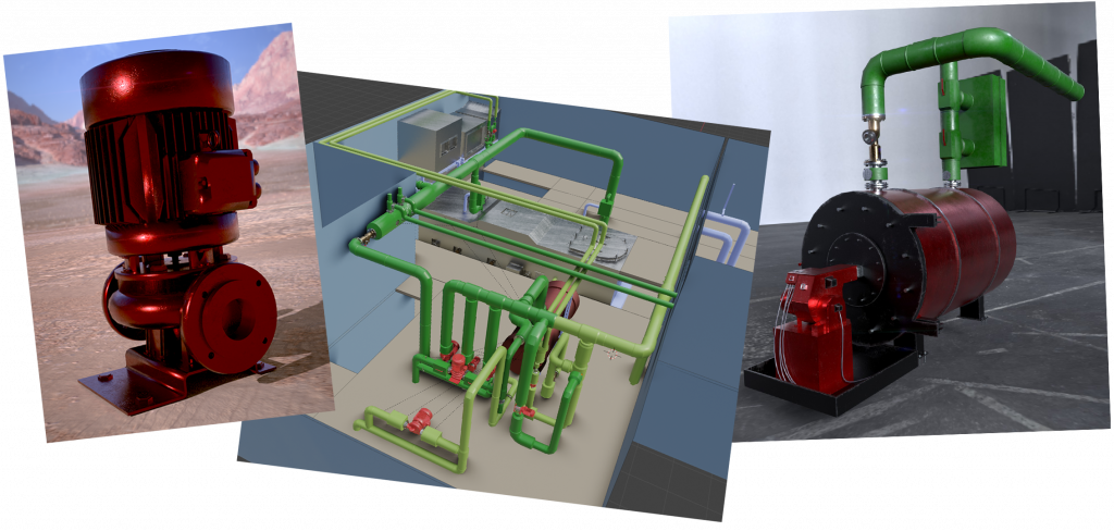
The strength of game engines is the efficient and fast implementation of the visual environments. They are particularly well suited for 3D modelling. In addition to the visual model, the digital twin contains functionalities that can also be found in the real-world counterpart. The most straightforward functionalities to be modeled are, for example, details related to the mechanical properties of the system. In the visual model of a heating plant, mechanical objects to be modeled include, for example, modeling of building doors, inspection hatches, manually adjustable valve handles and electrical switches. Modeling doors and inspection hatches involves a visual effect that the observer sees after some input information triggering the door opening has been provided. The input information can be a virtual operation of the user to open the door or some movement of the cursor by the user in the vicinity of a suitable visual key element.
The functional model can be implemented with a game engine
There are numerous different options for implementing a key element or measure. Behind the door, a view opens to another space and through the inspection hatch, a view inside, for example, a boiler. Depending on the operating mode of the system, the boiler can be passive or produce heating power. When the heating is active, the visual effect after opening the door can be, for example, a visible combustion reaction inside, i.e. flames of fire. In the real world, opening the inspection door may also be accompanied by an emergency alert or other similar process-related action. In a real-world situation, a cross-effect, for example, on a malfunction of a vacuum that takes care of the pressure difference in the furnace, can also cause smoke flaking out of the inspection hatch. As a combination of the functional scenarios of the digital model, a description of the process is created, which in the case of game engines has to be modeled and programmed with the accuracy and to the extent required in the model.
In addition to the visual effect, sufficient realism may also require the creation of sounds that corresponds to reality. The sound associated with the opening of the door itself and the sound world carried from another space enhances the immersion of the model, i.e. the sense of presence or realism felt by the user. The concept of immersion comes from the gaming industry and especially from experiencing virtual reality.
Producing a functional model requires modeling the process
Producing a functional model of a complex process requires an understanding of the basics of process modeling. Systems combining mechanical, thermodynamic, hydraulic, and electrical subsystems, for example, have typically been modeled by describing the subsystems individually or with tools suitable for process modeling, such as Matlab Simulink, Labview, or Ptolemy II. In these simulation programs, it is possible to implement a time model required by the processes.
The functional model of the process describes the progress of the process in real time
In the time model, the time of the process progresses in real time or even faster than the actual rate of occurrence. The subprocesses take place in order and by mimicking the chain of events of the actual process so that the dependencies, i.e. causality, are realistic. In this case, for example, the fuel entering the boiler burns and, as a result of the combustion, thermal energy is transferred to the liquid circulating in the system. In a district heating plant, the circulating liquid is water and, for example, in ground source heat pumps, a water-ethanol mixture. Modeling of the time model and process progression can be implemented in its simplest way by thinking of a stable operating point for the system, where all the functional elements to be modeled in the system have settled into a stable state.
For example, in the modelling of a heat plant, the steady state is one in which the temperature of the circulating liquid, the volume flow of the circulating water in the circuit, and the pressure differences in the piping and boiler systems are in a stable state. The heating plant model has two separate water circuits connected by a heat exchanger. Through the heat exchanger, the thermal energy of the primary water, i.e. the water heated in the boiler circuit, is transferred to the secondary circuit, i.e. the district heating network.
Progressing the process over time is worth doing simply
The functionality of the sample heating plant was modeled so that at the start of the simulation, all variables, i.e., temperatures, pressure differences, and flows, have zero initial values. The calculation of the stable operating mode starts from the pump of the primary or boiler circuit and first the pressure difference produced by this power is calculated on the basis of the power set on the pump. The calculation of the pressure difference is started from the numerical value zero and the pressure differences of all elements of the circuit are calculated in small steps and at each cycle the pressure is raised to a state where the pressure difference in the pump and the set pump power theoretically correspond to each other. The pressure information produced by the pump is transferred in each revolution to the next element in the primary circuit which is the pipe. In the simplest model, the pipes transfer the pressure difference directly forward to the next model as is, so there are no pressure losses in the pipes. The pressure drop for the pipes can of course be set as a parameter, but in the simplest model it is not necessary.
First, the static state of the process is determined
The calculation proceeds element by element and the pressure difference moves forward for each circuit element. The elements form a system in which, viewed in the direction of rotation, they have a pressure difference as input data and a pressure difference after the element as output data. If the element is a valve, the numerical value of the valve position as input data is checked and based on this the pressure change produced by the valve is calculated and passed to the next element as input data. When the entire circuit is computationally rotated element by element, the calculation proceeds to the second stage, where the flow and temperature losses of the water flowing in the circuit are calculated on the basis of the pressure difference, if they have been defined for that circuit element. The temperature of the liquid circulating in the circuit is determined on the basis of the boiler power data and the volume flow of the flowing water. The pressure differences, flows and temperatures of the elements of the secondary circuit are calculated in a similar way. In the secondary circuit, the calculation is started in the same way as in the primary circuit for the pump producing the pressure difference. There is no heating boiler in the secondary or district heating circuit, but it corresponds to the output connection of the heat exchanger, which produces the heating power of the primary circuit to the secondary circuit.
The static model is sufficient for some of the simplest modeling. A more realistic model also includes modeling the dynamic properties of the system. Dynamic properties are the change phenomena that occur in the system. Such dynamic properties include, for example, increases and decreases in boiler power and flow changes in the secondary or district heating circuit. Modeling the dynamic properties leads to solving the differential equations describing the system. The simplest model of the differential equation is the so-called first-order differential equation, the mathematical solution of which is an exponentially descending or ascending graph. For example, the boost circuit boost can be modeled with a first-order differential equation if, as a result of the boost, the circulating water temperature rises to some new temperature value without the temperature behaving unstably. For example, temperature oscillation is an example of instability. A first-order differential equation is often a sufficient model for the dynamic properties of a system.
The phenomena of change, i.e. dynamic properties, are modeled with differential equations
The functionality of a simple dynamic model can be determined, for example, by determining the time during which the temperature rise occurs, i.e. the time constant of the temperature rise rate, by means of a step response test. By determining the time constant, the temperature rise corresponding to the power increase and the delay in the system, i.e. the so-called dead time, a dynamic model sufficient for most practical cases can be implemented. The dynamic properties of the sample heating plant were modeled by performing the test runs of the heating plant on 25.5. – 27.5.2020. During the test times, e.g. stepwise boiler circuit power increases and district heating circuit flow changes. During the changes, changes in the temperatures and flows of the primary or boiler circuit and the secondary or district heating circuit, as well as pressure differences, were measured. Based on the test measurements, the dynamic properties of the heating center were determined using regression analysis methods. The models of dynamic properties calculated on the basis of test runs and measurements are transferred to a functional model describing the properties of the system by programming them in the game engine into the program code of the model. The programming language is the Unity 3D game engine C#.
The visual and functional model combines into a digital twin
The final digital twin combines a visual model and a functional model describing the functionality of the heating plant process into a single entity. The goal is to produce the desired functionalities feature by feature. Each increase in functionality develops the system in a more usable and real-world direction. The digital twin, in its more advanced form, can be in real-time communication with its physical counterpart, so that operating operations through the digital twin can even control its real-world counterpart or alternatively the real-world thermal power plant functional change is realistically reflected in the digital twin. For example, so that the popping of smoke in the real world is heard and seen in the virtual world. The smell of smoke in the virtual model is still a fictitious feature for the time being, but in the future, perhaps that too can be implemented.
Official name of the project: Digital twins for leveraging renewable energy
Project timetable: 01/01/2020 – 31/12/2022
Total budget: 761 732 €
Funding: EAKR 2014-2020
Contact person: Tauno Tepsa (+358 40 821 6865)


Tauno Tepsa
Tauno's work is divided into teaching and working as a Project Manager. He works in the DUKE project as a Project Manager. Tauno's special areas are Electronics, Embedded Software, Automation and IoT.